


Products
News
- ▶ Why Insulation Matters When Transporting Palm Oil in a 38 m3 Tanker
- ▶ 20 m2 Two-Compartment Fuel Tankers: Features That Matter to Resellers
- ▶ Planning Fleet Routes with a 20 m2 2-Compartment Fuel Tanker Truck
- ▶ Fuel Segregation and Discharge Controls for 20 m2 Two-Compartment Tankers
- ▶ Evaluating Compartment Split Ratios in a 20 m2 Fuel Tanker Truck
20 m2 Two-Compartment Fuel Tankers: Features That Matter to Resellers
A 20 m3 two-compartment fuel tanker should be evaluated as a working asset with two separate delivery streams, not simply as a 20,000-litre tank divided in half. Its purchase value comes from whether the compartment split, discharge arrangement, chassis specification, and tank construction suit the routes and fuel grades it will carry. A low initial quote can become expensive when the tank layout causes partial-load trips, difficult cleaning, premature corrosion, or repeated valve repairs.
The first cost question is therefore not “What is the price per cubic metre?” It is “How much usable payload and delivery flexibility does the specified layout preserve?” A two-compartment tanker often suits routes that supply two fuel products to the same area, or one larger customer order combined with several smaller drops. The arrangement loses value when both compartments are made equal by default but local order patterns are consistently uneven.
Compartment volume is a commercial specification
A nominal 20 m3 capacity does not establish the useful volume of each compartment. Equal 10 m3 sections are straightforward to manufacture and explain, but a 12/8, 13/7, or similar split may better reflect the fuel mix carried on regular routes. The right division should be based on recurring delivery quantities, expected product pairing, axle-load limits, and the need to keep one product separate from another.
Partition position also affects vehicle behaviour. Liquid load movement changes as each compartment fills or empties. Internal baffles reduce surge, but their design does not replace sensible compartment sizing. A tanker that is stable while fully loaded may behave differently during a multi-stop route when one compartment is nearly empty and the other remains full. The partition layout, baffle arrangement, and intended unloading sequence need to be reviewed together.
Ask for the stated capacity to distinguish between geometric volume and operational fill volume. Allowance may be needed for thermal expansion and safe filling practice. A quoted 20 m3 body should therefore be accompanied by a compartment drawing that identifies nominal volume, working volume, manhole position, baffle locations, and discharge outlets. Without this drawing, it is easy to compare two apparently similar quotations that do not represent the same usable arrangement.
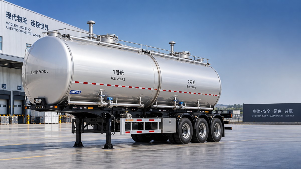
Separation has to continue beyond the tank shell
Two compartments only deliver genuine product separation when the fill, vent, outlet, and pipework arrangements are controlled independently. A partition inside the shell is not sufficient if shared piping creates a path for mixing, residue transfer, or incorrect discharge.
Each compartment should have clearly identified access and discharge points. Separate bottom outlets, dedicated valves, and a layout that lets the operator trace the product path reduce the chance of opening the wrong line during delivery. Where a common manifold is specified, its valve logic deserves particularly close attention. It may simplify external piping, yet it adds potential cross-connection points. The manifold should permit isolation, draining, and inspection without requiring improvised procedures.
Vent arrangement is equally important. During filling and discharge, each chamber needs a controlled air path. Poorly positioned or inadequately protected vents can create filling delays, product loss, contamination exposure, or pressure imbalance. The practical question is whether the venting design matches the loading method used at terminals and the discharge equipment used at delivery points.
Tank material and fabrication affect the cost after delivery
Fuel tanker material selection should follow the cargo, environment, cleaning method, and required tare weight rather than a generic preference for a particular metal. Carbon steel is widely used for compatible petroleum products and can be economical where fabrication quality and protective finishing are well controlled. Aluminium can reduce tare weight, but repair capability, welding practice, and local support should be considered before treating lower weight as an automatic advantage. Stainless steel has strong relevance in applications requiring hygiene or higher corrosion resistance, but it is not a universal substitute for a correctly specified fuel tank.
The contrast with a 20 m³ Stainless Steel Insulated Milk Tanker Truck illustrates why cargo conditions must drive the specification. A milk tanker may use 316L stainless steel, insulation, and sanitary internal finishes because product cleanliness and temperature management are central to its service. A fuel tanker requires its own compatible material, weld quality, sealing arrangement, and internal cleanliness standard; copying a food-liquid specification would not automatically improve fuel transport value.
Fabrication details reveal more than a material label. Tank shell thickness, end-plate thickness, stiffening design, weld procedure, and pressure testing all affect fatigue resistance and service life. Thin material can lower tare weight, but a shell that is insufficiently supported for rough roads, frequent loading cycles, or difficult yard conditions may develop distortion around supports, partitions, manholes, or outlet reinforcements. Excess material, on the other hand, reduces payload without necessarily improving the areas that experience the highest stress.
Inspect the transition between tank supports and chassis. This is a high-load interface, especially on uneven roads or where loading sites have poor surfaces. Saddles should distribute load without creating concentrated pressure points on the shell. Protective strips, support spacing, and restraint design matter because cracking or rubbing at this interface can be costly to correct after the tank is in service.
The running gear must match the loaded body, not the brochure capacity
A 20 m3 tanker body can be offered on different axle, suspension, tyre, and brake configurations. These choices affect permitted payload, ride stability, maintenance burden, and spare-parts planning. The loaded mass must be calculated from fuel density, tank tare weight, installed equipment, and the intended operating allowance. Capacity alone is not an axle-load calculation.
Component names should not be treated as a complete quality assessment. The mounting method, service access, specification sheet, and availability of replacement parts are just as relevant. For example, a familiar axle rating does not confirm that the wheel-end, brake chamber, suspension bracket, and tyre selection are suitable for the fully equipped tanker and route conditions.
Discharge equipment can create the largest operational differences
A fuel tanker’s discharge system should be specified around the actual delivery method. Bottom loading and bottom discharge arrangements may improve handling efficiency where compatible infrastructure exists, while top-loading operations create different access, overflow, and operator-safety considerations. The layout needs to account for hose reach, pump compatibility, outlet height, valve accessibility, and the order in which compartments are discharged.
Valve selection needs a clear purpose. Emergency shut-off devices, foot valves, API-style outlets, ball valves, and control valves are not interchangeable descriptions. Their suitability depends on the intended line arrangement and how the tanker will be isolated during loading, transport, and delivery. A requested valve list should identify its location and function, not merely give a count.
Small omissions often lead to field modifications: missing drain points, inadequate hose storage, inaccessible filters, poorly placed operating handles, or outlet clearances that conflict with the chassis. These changes are harder to make after painting and delivery, and they can compromise the original layout. A general arrangement drawing showing the tank, discharge side, pipe routing, spare-wheel position, toolbox, mudguards, and rear protection is more useful than a list of accessories alone.
Documents that reduce specification disputes
The technical offer should describe the body as a complete configuration. It should state compartment capacities and tolerances, material grades and thicknesses, tank test method, baffle and partition layout, manhole and vent details, pipework material, valve type, chassis dimensions, axle and suspension ratings, tyre specification, braking arrangement, landing gear, kingpin, and coating system where applicable.
Approved drawings should be treated as part of the order record, especially where dimensions must suit local tractors, terminals, or loading racks. A change in tank diameter, rear discharge position, landing gear placement, or chassis height can affect coupling clearance and access. Confirming these interfaces before fabrication is usually less disruptive than correcting them after shipment.
For a 20 m3 two-compartment fuel tanker, the strongest specification is the one that ties cargo split, route pattern, liquid-control hardware, and running gear into a single usable design. That approach makes quoted differences easier to interpret and prevents apparently minor details from becoming long-term cost issues.
Get Quote Form
Please complete the form below, and our product experts will contact you within one business hour. All inquiry details are kept strictly confidential and used solely to provide you with a precise solution.
✅ 24/7 Engineer Online Support | Ready for any technical inquiries.
✅ Full Export Documentation Support | We provide full set of shipping documents to ensure smooth customs clearance.
LOGO
This stunning beach house property is a true oasis, nestled in a serene coastal community with direct access to the beach.
Opening Hours
Monday - Friday : 9AM to 5PM
Sunday: Closed
Closed during holidays
Contact
+18888888888
hezuo@eyingbao.com123 West Street, Melbourne Victoria 3000 Australia
Request a Free Quote Today
Need mainstream models or custom specs? Our engineers are ready.
Contact us today for a lasting partnership!