


Products
News
- ▶ Carbon Steel Oil Tanker Trailers: Selecting Plate Thickness for Payload and Durability
- ▶ Oil Tanker Trailer Price Trends: How Steel, Aluminum, and Component Costs Move
- ▶ When Does a Higher-Priced Oil Tanker Trailer Reduce Downtime and Repair Risk?
- ▶ Comparing Oil Tanker Trailer Quotes: A Checklist for Like-for-Like Pricing
- ▶ How Tank Material, Axles, and Safety Systems Affect Oil Tanker Trailer Prices
Carbon Steel Oil Tanker Trailers: Selecting Plate Thickness for Payload and Durability
Plate thickness in a carbon steel oil tanker trailer should not be chosen from capacity alone. A tanker that appears adequately built on paper can still lose payload efficiency, develop fatigue around supports, or corrode prematurely if the shell, end plates, and compartment bulkheads are not matched to the actual fuel, route, and operating cycle. The correct starting point is to define the liquid load and structural duty, then select thickness with a deliberate corrosion allowance rather than simply choosing the heaviest available plate.
This decision becomes especially important when a fleet operates on mixed road surfaces, carries dense fuels, uses multiple compartments, or expects a long service interval between major repairs. Thicker plate can improve reserve strength and corrosion life, but it also increases tare weight. That added weight reduces legal payload margin and can change axle loading. A thinner shell may improve payload, yet it demands tighter control of fabrication quality, internal bracing, corrosion protection, and operating conditions.
Begin with the real loading condition, not nominal tank volume
A 40 m³ or 45 m³ tanker does not impose one fixed load on the tank structure. Fuel density varies by product and temperature, and compartment loading may not be uniform. Diesel, gasoline, kerosene, and blended petroleum products can produce different gross liquid weights at the same fill volume. The design review should therefore use the heaviest intended liquid, the maximum permitted fill level, and the likely compartment arrangement.
Technical evaluators should also consider dynamic loading. A fully loaded tanker on smooth highway pavement experiences a different duty cycle from a tanker that regularly passes through rough access roads, uneven depot yards, steep ramps, or areas with frequent braking and turning. Liquid surge transfers load to the shell, bulkheads, manhole region, supports, suspension connection points, and kingpin area. Plate thickness is one part of resisting these forces; compartment spacing, baffle design, weld layout, and chassis support geometry are equally important.
- Static liquid pressure: increases toward the lower shell and depends on liquid density and liquid height.
- Surge and braking loads: act repeatedly on compartment bulkheads and end plates.
- Road-induced fatigue: concentrates around saddle supports, longitudinal members, and welded transitions.
- Local attachments: manholes, discharge outlets, pipe brackets, ladder supports, and rear frames require reinforced detailing.
Where thickness matters most on the tank
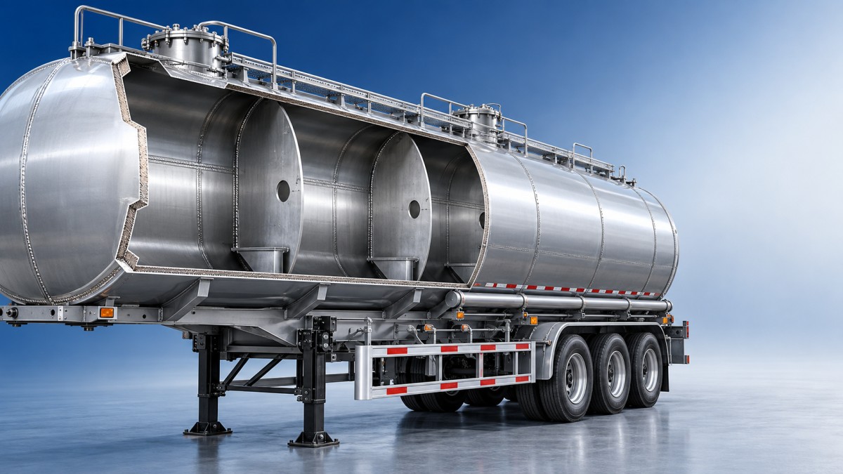
It is rarely appropriate to evaluate the entire tank using one shell thickness figure. Different zones face different stresses. The cylindrical shell carries liquid pressure over a large area, while the front and rear end plates receive shape-dependent stress and may require a heavier section. Compartment bulkheads manage liquid separation and surge loading. Areas around openings need local reinforcement because cutting a manhole, vent, outlet, or inspection port interrupts the load path.
A specification review should request separate values for the shell, end plates, bulkheads, and any reinforcement pads. Asking only for “tank plate thickness” can hide a weak point in the overall structure. A tank with a well-selected shell plate but insufficient end-plate thickness or poor reinforcement around the discharge system may still become a maintenance concern.
Corrosion allowance should reflect the whole operating environment
Carbon steel remains a practical tank material where fuel compatibility, repair access, cost control, and fleet maintenance capability support its use. Its long-term durability, however, depends on managing corrosion from both inside and outside the tank. Plate thickness should include a realistic reserve for expected material loss, but a corrosion allowance is not a substitute for surface preparation, coating quality, drainage, and inspection.
Internal corrosion risk depends on product cleanliness, water contamination, sediment, and how long residual liquid remains in compartments. Water accumulation can create localized corrosion at low points and around outlet areas. Externally, road spray, coastal humidity, abrasive dust, damaged paint, and trapped moisture around brackets or support interfaces can accelerate deterioration. A tanker serving dry, paved routes may justify a different balance than one working around ports, unpaved fuel stations, or regions with aggressive seasonal weather.
During evaluation, confirm whether the quoted thickness is the actual supplied plate thickness before forming, the nominal finished thickness, or a minimum acceptable value after manufacturing tolerance. Also ask how weld seams are protected, whether internal surfaces are prepared for the intended fuel service, and how water drainage is managed. These details determine whether the theoretical corrosion allowance remains available during service.
Do not solve every durability concern by making the shell heavier
Increasing carbon steel thickness can be sensible when route severity, tank geometry, corrosion exposure, or required operating life creates a clear structural need. But it should not be used to compensate for weak chassis design, poor weld control, inadequate supports, or poor load distribution. An unnecessarily heavy shell raises empty weight across every trip, and the penalty is permanent. It may also move the vehicle closer to axle limits before the tank reaches its intended volume.
The better approach is to review the tank and trailer as a system. Confirm the number and position of supports under the tank, the load transfer into the chassis, axle group capacity, suspension configuration, brake specification, and kingpin loading. A high-volume tanker can have adequate gross capacity while still producing unfavorable axle distribution when compartments are filled in certain sequences. This is especially relevant for multi-compartment equipment, where partial loads and delivery order can shift the center of gravity.
Questions that expose an incomplete thickness specification
- Which liquid density was used for the structural calculation?
- Is the quoted shell thickness the same across the complete cylindrical body?
- Are end plates and bulkheads thicker than the shell, and why?
- What reinforcement is provided around manholes, outlets, and pipe supports?
- How does the manufacturer account for road vibration and repeated braking cycles?
- What corrosion protection is applied internally and externally?
- How does the specified tare weight affect payload and axle loading under full fuel load?
Use route severity to set the practical durability margin
For tanker work that is predominantly highway-based, a lighter carbon steel construction may be appropriate when the tank geometry, support arrangement, and corrosion protection are properly engineered. The goal is not minimum thickness at all costs; it is adequate structural capacity with useful payload efficiency. Controlled loading practices and regular inspection become more important as material reserve is reduced.
For routes with rough pavement, depot entrances with sharp level changes, repeated short-haul cycles, or frequent operation near corrosive environments, additional plate reserve can be justified. In these conditions, evaluate not only shell thickness but also end-plate reinforcement, bulkhead structure, support saddles, chassis stiffness, and protection of external welds. A fatigue crack usually begins at a local stress concentration, not in the middle of an otherwise sound shell.
There are also cases where reducing tanker tare weight is the dominant operational requirement. Aluminum alloy tankers can offer a different payload-to-weight balance, although their material behavior, repair methods, and structural detailing must be assessed separately from carbon steel. For comparison in a high-volume, multi-compartment configuration, the 45 m³ 6-Compartment Aluminum Alloy Oil Tanker Semi-Trailer uses a 5.5 mm 5454 aluminum alloy tank body and 7 mm end plates. Those figures should not be transferred directly to a carbon steel design: alloy type, strength, density, welding characteristics, and corrosion behavior are different. The useful lesson is to compare complete tank architecture rather than plate numbers in isolation.
Review fabrication evidence before approving a thickness
A reliable plate specification is supported by manufacturing controls. Material certificates should identify the steel grade and supplied thickness. Forming procedures should avoid excessive thinning at curved sections. Weld procedures should be suitable for the tank material and joint design, with inspection focused on seams, bulkheads, openings, and attachments. Pressure or leak testing confirms containment integrity at delivery, but it does not replace a review of structural detail.
Pay particular attention to transitions where thick reinforcement meets thinner plate. Abrupt changes in stiffness can concentrate fatigue stress if the detail is poorly designed. The same applies to brackets welded directly onto the shell. Where practical, loads from walkways, piping, and accessories should be distributed through properly designed supports rather than concentrated in a small shell area.
A workable selection sequence
- Define the maximum-density product, tank volume, compartment loading pattern, and legal gross-weight limit.
- Classify the route by pavement quality, gradients, braking frequency, delivery-site access, and corrosion exposure.
- Review shell, end plate, bulkhead, and reinforcement thicknesses separately.
- Check tare weight and axle distribution at full load and representative partial-load conditions.
- Verify corrosion protection, drainage details, weld inspection, and accessibility for future maintenance.
- Compare alternative material options only after confirming that each design meets the same operating duty.
The preferred carbon steel oil tanker trailer is not automatically the one with the thickest plate. It is the one whose thickness distribution, corrosion reserve, reinforcement details, and chassis integration match the heaviest intended load and the actual operating environment without sacrificing unnecessary payload. Where the duty cycle is severe or the local approval requirements are specific, the final plate schedule should be confirmed against the applicable transport rules and the manufacturer’s structural design documentation.
Get Quote Form
Please complete the form below, and our product experts will contact you within one business hour. All inquiry details are kept strictly confidential and used solely to provide you with a precise solution.
✅ 24/7 Engineer Online Support | Ready for any technical inquiries.
✅ Full Export Documentation Support | We provide full set of shipping documents to ensure smooth customs clearance.
LOGO
This stunning beach house property is a true oasis, nestled in a serene coastal community with direct access to the beach.
Opening Hours
Monday - Friday : 9AM to 5PM
Sunday: Closed
Closed during holidays
Contact
+18888888888
hezuo@eyingbao.com123 West Street, Melbourne Victoria 3000 Australia
Request a Free Quote Today
Need mainstream models or custom specs? Our engineers are ready.
Contact us today for a lasting partnership!